
This article discusses the Secondary Air Injection (SAI) system for the Audi C5 A6. We wrote this focused on the 4.2 V8 model as made from 1999 to 2004, with the main focus being on how the system was designed, and why. For the 2.7 Turbo, the same principles apply plus it’s more complex yet. If you’re not here for the technical analysis but would rather buy a used unit from us, guaranteed to work and fit, then please select the link below:
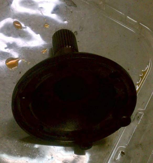
- Secondary air injection pump (Bosch 0580000023), as on: C5 A6 2.7 Turbo, Part Number: 078906601H
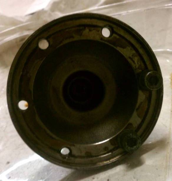
- Secondary air injection pump, as on: C5 A6 4-door 4.2, Part Number: 078906601M
The information herein is based on our own 4.2 V8 cars.
When a car with an internal combustion engine is at normal operating temperature, it’s very clean emissions-wise. The catalytic converter is part of the reason why. It changes the chemical composition of the exhaust gas to something that’s nicer to breathe.
However, when the engine is cold, it needs a more-rich fuel mixture so as to run, and when the catalytic converter is cold then it doesn’t work as well as when it’s at normal operating temperature. So, that’s a double whammy that make the exhaust gases less clean, when the engine is cold.
The folks at Audi used a clever design on the C5 Audi A6 to solve this problem. When the engine is cold, they artificially pump vast amounts of air into the exhaust system, using a high-volume blower (as in, a fan that pumps air). This helps the catalytic converter work better until it reaches normal operating temperature. This system is called “secondary air injection” a.k.a. “SAI.”
When the SAI system doesn’t work right, sensors in the car pick up on this and then the car turns on the “check engine” light in the instrument cluster, warning the driver that an emission-related process has failed.
To find out the specific reason behind the check engine light coming on in our project car, I connected my MS Windows laptop PC to the Audi and asked, “What’s wrong?” It replied: “My SAI is messed up” … essentially. For the dialog, I needed a special cable. One end plug into the Audi and the other end plugs into any Universal Serial Bus (USB) port in my laptop PC. I also needed some special software. I got both from a company called Ross-Tech. They’re beyond brilliant.
In its simplest form, the design of a SAI would involve the engine management computer sensing that the engine is cold and then turning on a blower. The blower would simply suck air from wherever it can get it, dirty or otherwise, and pump it into the exhaust system anywhere upstream of the catalytic converter.
There are several problems with this simplified design.
1. Pumping dirty air (e.g., with road dust) through the blower and into the catalytic converter would shorten the life span of both.
2. The blower would be very noisy, sounding like a vacuum cleaner on steroids.
3. The blower uses a lot of current so it’d need a thick set of wires to and from the computer, and a big, strong switch.
4. Once the engine reaches normal operating temperature, then the process would reverse, and air from the exhaust would escape out of the blower, which would destroy it, make a huge noise and pollute more.
5. If there were a problem in the wiring, the computer could easily be damaged.
So, our design would need to be improved:
1. The air would have to be sucked out of the clean air flow downstream of the air filter.
2. The blower would have to be located below the car and as far forward as reasonably possible, away from the passengers. Below the air filter happens to be just such a place, yay!
3. Instead of running heavy-duty wires from the blower to the computer, we would use a relay to handle the switching. That means we can have light duty wires from the computer turn on a little switch inside the relay which in turn, um, turns on the big switch. That’s what a relay is: a little switch that turns on the big switch.
4. We need some sort of valve that opens when the SAI system is active (such as when the engine is cold) and closes when it’s not active (such as when the engine reaches normal operating temperature)
5. A heavy-duty fuse would protect the computer in case of a wiring malfunction
Better.
Instead of one valve, we should have two, one for each bank (a.k.a. half) of the V8 engine — because it has two separate exhaust systems, one for each bank.
The computer would turn on the SAI system electrically. However, the valves are near the exhaust gas so they’ll get hot. Heat doesn’t play well with electrical components. So a vacuum-actuated valve system would be more reliable.
Better would be if the electrical signal would turn on a component that’s placed far away from the valves. The component would allow vacuum to reach the valves via a vacuum hose that runs to each valve. When there’s vacuum in the hose, the valve opens. This type component is called a solenoid.
… and that described the the SAI system on the Audi C5 A6, so now we know why it was designed as it is. Clever!


You must be logged in to post a comment.