
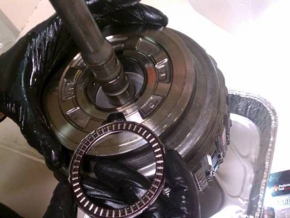
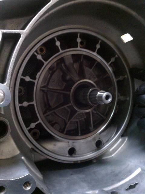
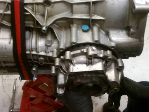
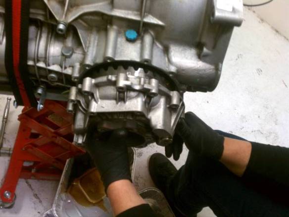
With the transmission upside down, and the oil plan removed, the valve body is easily accessible. An electrical cable runs along the outside of the valve body, from an external connection plug, to the solenoids and the pressure regulators along the front of the valve body.
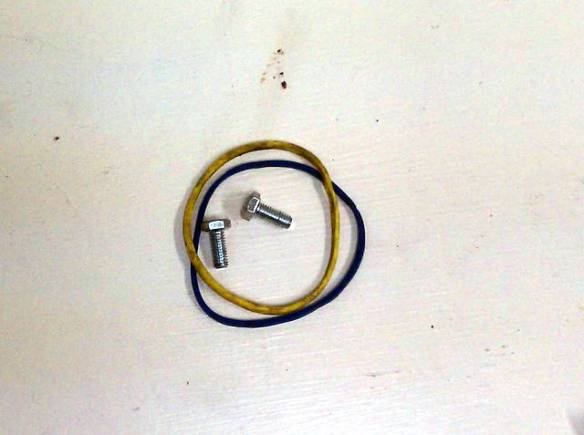
To separate the valve body from the transmission, we first removed the filter, by removing two T-27 Torx bolts.

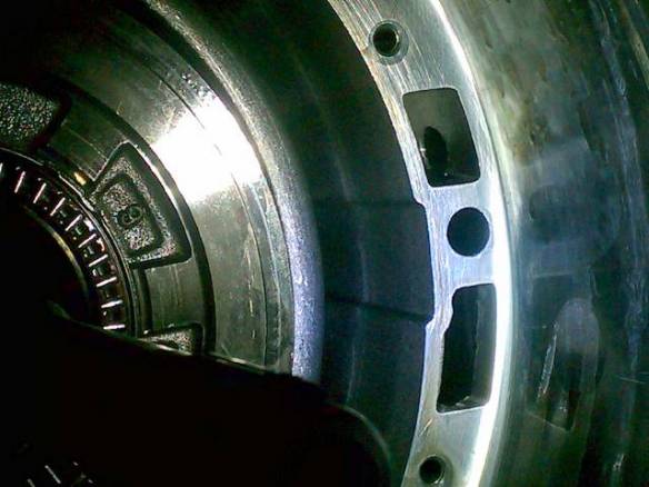
Then, we loosened the electrical plug. We identified and removed the T-27 Torx bolts that attach the valve body to the transmission.

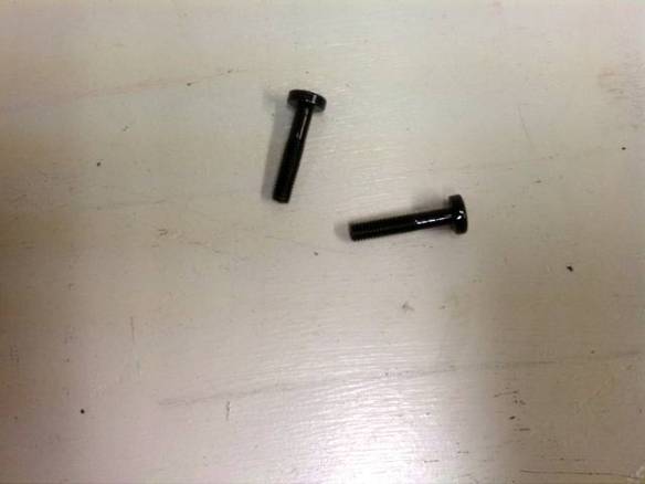
This is fairly tricky because we did not want to also remove the bolts that keep the valve body together. However, these bolts are the same color, and they are also T-27 Torx bolts. The difference is that that the T-27 Torx bolts that attach the valve body to the transmission have heads that have a slightly larger circumference.
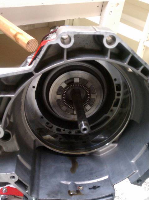
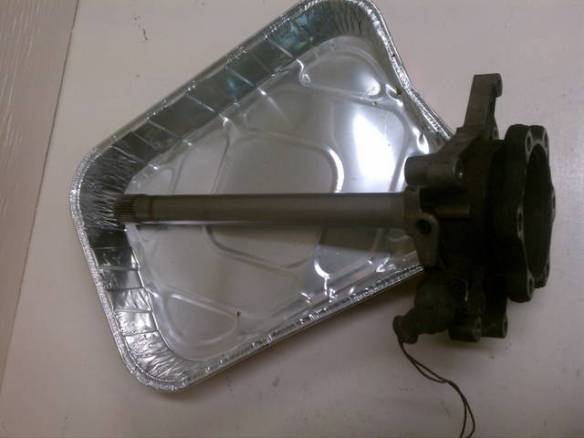
We had a gentle, clean spot ready for the valve body after we removed it, so that we did not have to set it down on a hard surface. Doing so might not have been very good for the speed sensor and the other fragile-seeming parts.
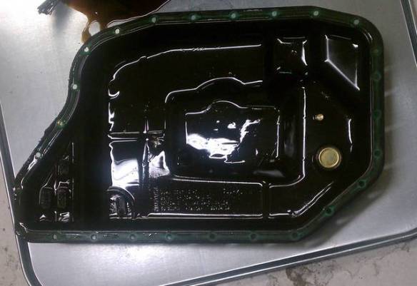


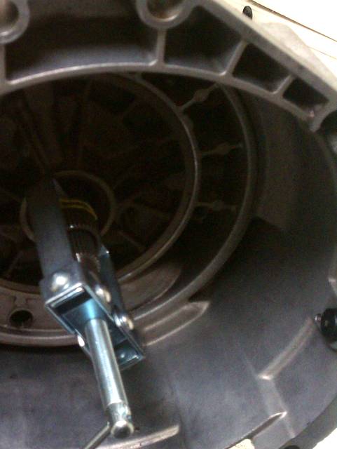
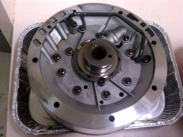

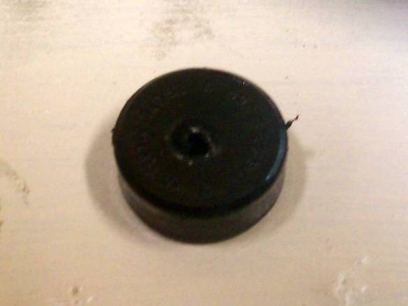


 Here’s the part, sitting in a drip tray.


You must be logged in to post a comment.